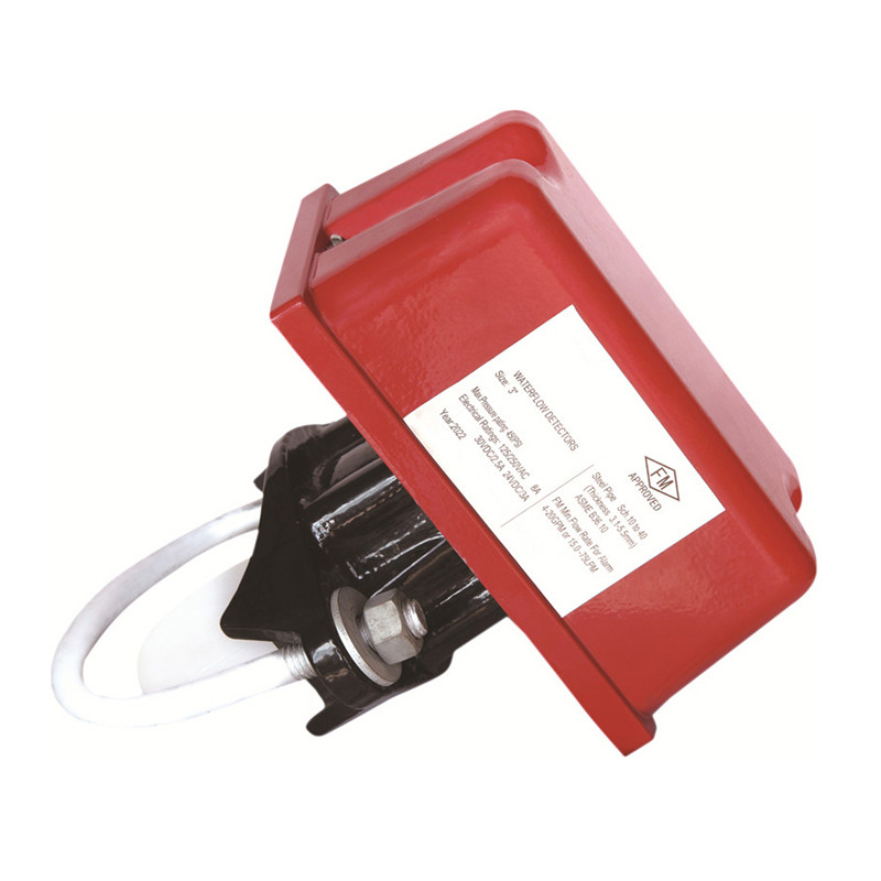
Water flow indicator UL/FM Approved
Overview:
The vane type waterflow switch use in wet pipe systems only. Waterflow in the pipe deflects a vane, which produces a switched output usually after a specified delay.
Main components:
Water flow indicator is mainly composed of the saddle, blade rack, bottom plate, outer cover, air delay device, micro-switch, junction box, etc.
| Main Dimensions of Water Flow Indicator | ||
| Specification | L | H |
| DN50 | 85 | 188 |
| DN65 | 92 | 200 |
| DN80 | 106 | 220 |
| DN100 | 134 | 245 |
| DN125 | 162 | 272 |
| DN150 | 189.5 | 298 |
| DN200 | 240 | 350 |
| 1 | Body | ASTM A536 65 45-12 |
| 2 | Blade rack | S.S.304+EPDM |
| 3 | Bottom plate | S.S.304 |
| 4 | Outer cover | ASTM B85 A03600 |
| 5 | Air delay device | Component |
| 6 | Blade | LLDPE |
| 7 | Micro-switch | Component |
| 8 | Sealing gasket | EPDM |
| 9 | Junction box | PC |
Installation of water flow indicator:at the pre-set installation position, use a tapper to drill on the main pipeline and remove burrs according to the product specification;roll up the blade into a small size and put it into the pipeline, install the U-shaped bolt and fasten it up with two fastening nuts.
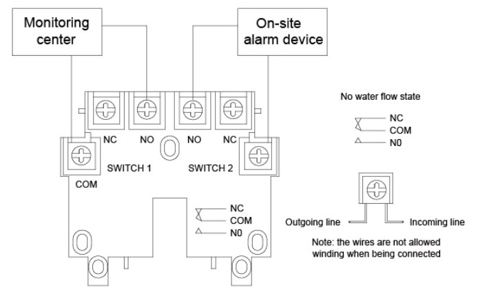
Wiring: The typical wiring diagram is shown
When drilling the hole, the center of the hole has to be on the center line of the pipeline;The hole size is shown.
| Specification | Hole size |
| DN50, DN65 | 32+2mm |
| DN80-DN200 | 51 +2mm |