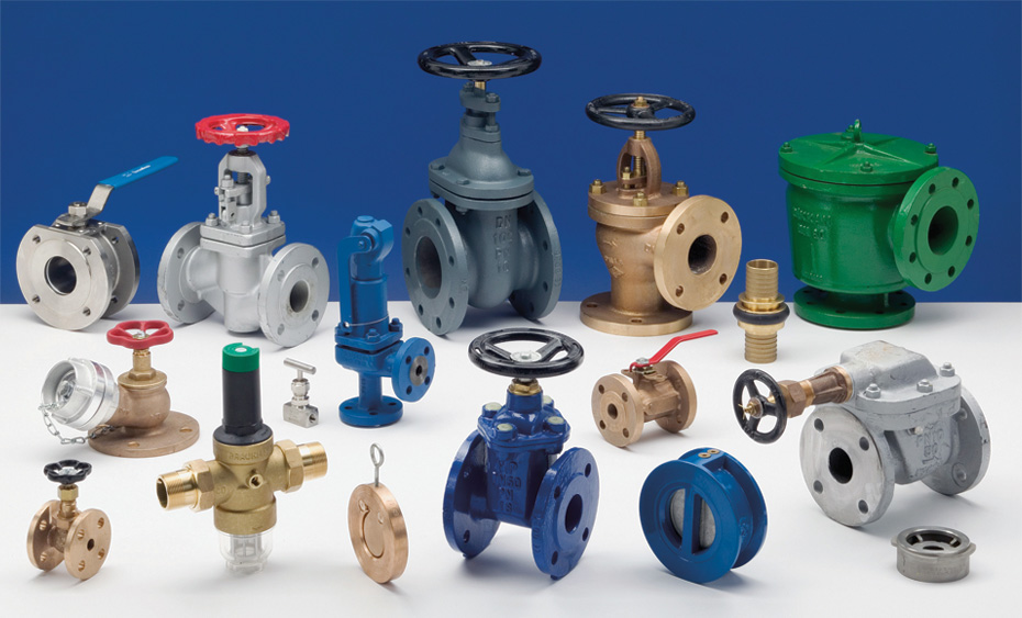
Suitable for the setting of gate valve, globe valve, ball valve, butterfly valve and pressure reducing valve in petrochemical equipment. Check valve, safety valve, regulating valve, trap set see the relevant regulations. Not suitable for the setting of valves on underground water supply and drainage pipes.
1. Valve layout principles
1.1 Valves shall be set according to the type and quantity shown in the PID flow chart of piping and instrumentation. When the PID has specific requirements for the installation position of some valves, it should be set according to the process requirements.
1.2 Valves should be arranged in a place that is easy to access, easy to operate and easy to maintain. Valves on rows of pipes should be centrally arranged, with operating platforms or ladders considered.
2. Valve installation position requirements
2.1 Cut-off valves shall be set up when the pipe gallery pipelines of the inlet and outlet devices are connected with the master of the pipe gallery of the whole factory. The installation position of the valve should be centrally arranged on one side of the device area, and the necessary operating platform or maintenance platform should be set up.
2.2 Valves requiring frequent operation, maintenance and replacement shall be located in an area easily accessible to the ground, platform or ladder. Pneumatic and electric valves should also be arranged in easily accessible places.
2.3 Valves that do not need to be operated frequently (only for opening and stopping) should also be placed in a place where temporary ladders can be erected if they cannot be operated on the ground.
2.4 The center of the valve handwheel should be 750 ~ 1500mm away from the operating surface, and the most suitable height is 1200mm. The installation height of the valve that does not need frequent operation can reach 1500 ~ 1800mm. When the installation height cannot be reduced and frequent operation is required, the operating platform or tread should be set in the design. Valves on pipelines and equipment with dangerous media shall not be set within the height range of human head.
2.5 When the center of the valve handwheel is more than 1800mm from the height of the operating surface, it is appropriate to set the sprocket operation. The chain of the sprocket should be about 800mm from the ground, and the chain hook should be set to hang the lower end of the chain on the nearby wall or post, so as not to affect the passage
2.6 For the valve installed in the trench, when the trench cover is open and can be operated, the handwheel of the valve should not be lower than 300mm below the trench cover. If it is lower than 300mm, the extension lever of the valve should be set so that the handwheel is less than 100mm below the trench cover.
2.7 When the valve installed in the pipe groove needs to be operated on the ground, or the valve installed under the upper floor (platform), the valve extension rod can be set to extend to the ditch cover plate, floor and platform to operate, and elongation rod hand wheel distance operating surface 1200mm is appropriate. Valves with nominal diameters of DN40 or less and threaded connections should not be operated with sprockets or extender rods to avoid damage to the valve. In general, valves should be operated with as little sprocket or extension rod as possible.
2.8 The distance between the valve hand wheel arranged around the platform and the edge of the platform should not be greater than 450 mm. When the valve stem and handwheel reach the top of the platform and the height is less than 2000 mm, it should not affect the operation and passage of the operator, so as not to cause personal injury.
3. Large valve setting requirements
3.1 The operation of large valves should use gear transmission mechanism, and the space position required by the transmission mechanism should be considered when setting.
3.2 Support should be set on one side or both sides of the valve for large valves. The support should not be located on the short pipe that needs to be removed during maintenance, and the support of the pipeline should not be affected when removing the valve. Generally, the distance between the support and the valve flange should be greater than 300mm.
3.3 The installation position of large valves should have a site for using crane, or consider setting davit and hanging beam.
4. Requirements for valves on horizontal pipes
4.1 Except for the special requirements of the process, the valve handwheel installed on the general horizontal pipeline shall not be downward, especially the valve on the dangerous medium pipeline is strictly prohibited. The orientation of the valve handwheel is determined in the following order:Vertical upward;和orizontal;vertical upward left and right tilt 45°;vertical downward left and right tilt 45°;not vertical downward.
4.2 Horizontally mounted rising stem valve, when the valve is opened, the valve stem shall not affect the passage, especially when the valve stem is located in the head or knee of the operator.
5. Other requirements for valve setting
5.1 The center line of valves on parallel pipes should be as neat as possible. When the valve is arranged next to each other, the clear distance between the handwheels should not be less than 100mm; Valves may also be staggered to reduce pipe spacing.
5.2 The valve required to be connected to the equipment nozzle in the process should be directly connected to the equipment nozzle when the nominal diameter, nominal pressure and sealing surface type are the same or matched with the equipment nozzle flange. When the valve is a concave flange, it is necessary to ask the equipment professional to configure the convex flange at the corresponding nozzle.
5.3 Unless the process has special requirements, the valves on the bottom pipes of towers, reactors, vertical vessels and other equipment shall not be arranged in the skirt.
5.4 When the branch pipe is drawn from the main pipe, the cut-off valve should be located on the horizontal section of the branch pipe near the root of the main pipe, so that the fluid can be drained to both sides of the valve.
5.5 The branch pipe cut-off valve on the pipe gallery is not often operated (only for stopping and maintenance). If there is no permanent ladder, space should be set aside for the use of temporary ladder.
5.6 When the high-pressure valve is opened, the starting power is large, and the support must be set to support the valve and reduce the starting stress. The installation height should be 500 ~ 1200mm.
5.7 The fire water valve and fire steam valve in the boundary area of the device should be distributed in a safe area the operator is easy to access in the event of an accident.
5.8 The valve group of the fire extinguishing steam distribution pipe of the heating furnace should be easy to operate, and the distance between the distribution pipe and the furnace body should not be less than 7.5m.
5.9 When installing a valve with threaded connection on the pipe, a live joint must be installed near the valve for disassembly.
5.10 The clamp valve or butterfly valve shall not be directly connected with the flanges of other valves and fittings, and a short pipe with flanges at both ends should be added in the middle.
5.11 The valve should not bear external load, so as not to damage the valve due to excessive stress.
Post time: Feb-02-2023